Choosing the 2026 best electrical switchgear requires more than comparing prices, ratings, or polished product images. The practical question is: what is electrical switchgear, and why does it matter in modern power systems? Electrical switchgear combines switching, protection, control, and isolation equipment. It helps manage electricity safely across factories, commercial buildings, data centers, utilities, and renewable energy installations.
A well-designed switchgear lineup may include circuit breakers, disconnectors, fuses, busbars, relays, meters, and protective controls. Each component has a specific role. During a fault, the system must interrupt current quickly and limit damage. During maintenance, it must provide a clearly visible isolation point. Small details matter. A loose connection, poor enclosure seal, or incorrect relay setting can create serious operational problems.
This guide examines leading switchgear types, technologies, applications, and selection factors for 2026. It considers voltage level, fault capacity, environmental conditions, arc-flash protection, service access, monitoring, and lifecycle support. Field experience shows that the “best” product depends on the installation, not only the manufacturer’s reputation. That point is easy to overlook.
Reliable evaluation also requires current technical documentation, qualified engineering review, and compliance with applicable standards and local requirements. Product claims should be verified through test reports, certifications, maintenance records, and supplier support. Some newer digital features appear impressive, but they may add complexity without improving every project. A careful comparison should question both established habits and attractive innovations. Safety comes first. Performance must remain measurable.
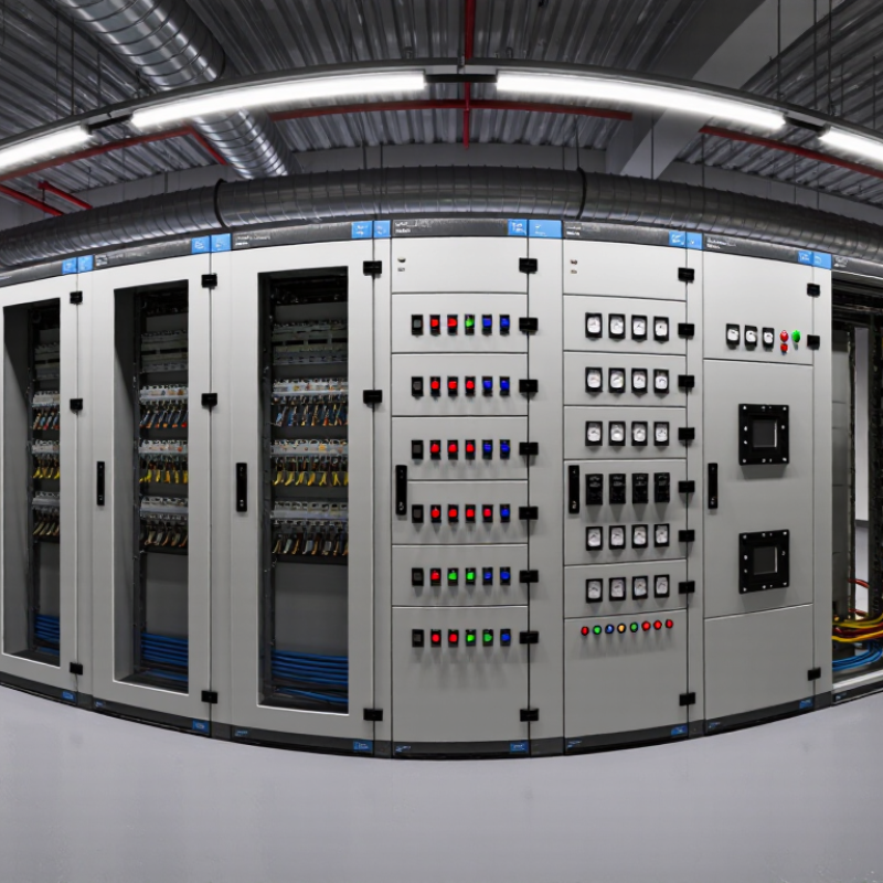
Electrical switchgear is an engineered assembly that controls, protects, and isolates electrical circuits. It may include circuit breakers, fuses, disconnectors, busbars, relays, and measurement devices. Its purpose is practical: stop fault current, direct power safely, and allow technicians to work on isolated equipment.
You may find it in commercial buildings, factories, data rooms, and utility distribution panels. A molded-case circuit breaker can interrupt overloads, while a protective relay may monitor current, voltage, or ground faults. Clear labeling matters. So does space. Crowded terminals make inspection and maintenance harder.
and demands stricter insulation, clearance, grounding, and access controls. Air-insulated and gas-insulated designs use different construction methods, but both require verified fault ratings and tested interlocking. During field inspections, technicians check contact wear, insulation condition, mechanical movement, and stored-energy mechanisms. A clean enclosure is helpful, but it proves little by itself. Testing must follow the equipment rating and applicable standards.
The boundary looks simple.
In practice, terminology can vary by region and standard. Some systems describe a middle range as medium voltage, even though it remains above 1 kV. Engineers should confirm voltage class, short-circuit withstand, installation conditions, and maintenance procedures before selecting equipment.
A switchgear label may be accurate yet incomplete. That is an easy detail to overlook.
In 2026, the best electrical switchgear is not simply the largest or newest cabinet. It is a coordinated system that controls, protects, and isolates electrical circuits safely. Inside the enclosure, breakers manage fault interruption, while busbars distribute power across connected feeders. Clearances matter. During commissioning, technicians check insulation, torque values, interlocks, and mechanical operation before energizing the equipment.
Breakers interrupt abnormal current and protect cables from severe damage. Busbars carry high current through a compact, low-resistance path. Current transformers, or CTs, reduce primary current for metering and protection circuits. Protection relays interpret CT signals and send trip commands when they detect overloads, short circuits, or ground faults. Together, these components form the switchgear’s operating logic. However, settings must match the actual network. One incorrect relay value can delay tripping or cause an unnecessary outage.
Experienced engineers verify drawings against the installed cabinet, not assumptions. Thermal scans can reveal loose connections after the system carries load. I have found small temperature differences that inspections missed. That result deserves attention, but it is not absolute proof of failure. Good documentation records test currents, relay settings, breaker timing, and inspection dates. No checklist replaces judgment. Real installations contain dust, vibration, heat, and human mistakes, so maintenance plans should reflect those conditions.
2026 Best Electrical Switchgear: What Is It?
Switchgear Types: AIS, GIS, and Hybrid Systems from 12 to 550 kV
Electrical switchgear controls, protects, and isolates power networks. Its selection depends on voltage, space, climate, safety, and maintenance access. The IEC 62271 series provides key requirements for high-voltage assemblies. AIS uses air insulation and suits many 12–145 kV substations. It offers visible equipment and simpler inspection. However, it needs more land and careful pollution control. GIS encloses energized parts inside grounded metal compartments. It can reach 550 kV while reducing the substation footprint dramatically. Hybrid systems combine air-insulated busbars with compact gas-insulated modules. They often fit extensions where space is limited.
The IEA Electricity 2024 report forecasts global electricity demand growth of about 3.2% annually from 2024 to 2026. Renewable generation is expected to meet most additional demand. That shift increases switching operations, fault-control needs, and grid connection pressure. At 12 kV, operators may prioritize modular maintenance and feeder protection. At 550 kV, insulation coordination, transient recovery voltage, and proven testing become critical. Gas management also requires attention, especially where fluorinated insulation gases are used. The neatest design is not always the most reliable one. A compact bay can still create difficult repair access.
Tips: Compare total lifecycle cost, not purchase price alone. Check altitude, humidity, salt, seismic conditions, and local service skills. Ask for type-test evidence under IEC 62271. Leave room for future feeders. That detail is often forgotten.
Representative voltage coverage of Air-Insulated Switchgear (AIS), Gas-Insulated Switchgear (GIS), and Hybrid Systems across commonly used high-voltage classes from 12 to 550 kV.
AIS uses air as the primary insulation medium and is generally easier to inspect and extend, but requires more installation space. GIS uses a sealed gas-insulated enclosure for a compact footprint and is widely applied where space, pollution, or environmental conditions are challenging. Hybrid systems combine air-insulated and gas-insulated sections to balance footprint, accessibility, and cost. The voltage ranges shown are representative engineering ranges; actual configurations depend on applicable IEC standards, system design, and project requirements.
The best electrical switchgear is not defined by appearance or price. It must match the installation’s voltage, load profile, protection scheme, and fault environment. Frequency matters too: equipment designed for 50 Hz may require different verification at 60 Hz. Engineers should check tested performance, not rely on catalogue wording alone.
A short-circuit rating of 16–63 kA indicates the prospective fault current the assembly can withstand or interrupt, depending on the stated rating. These values are not interchangeable. Breaking capacity, short-time withstand current, and peak withstand current describe different duties.
A 1–3 second fault-duty rating shows how long the equipment can carry severe current before protective clearing. Longer duration creates more thermal and mechanical stress. Small details matter.
During site reviews, technicians often compare the nameplate with cable calculations, upstream protection, and actual transformer capacity. They also inspect busbar joints, shutters, earthing connections, and temperature-rise evidence. Poor ventilation can reduce practical performance, even when the laboratory rating looks suitable. This is where selection becomes less certain. The phrase “best switchgear” can mislead engineers if operating conditions remain unclear. Altitude, humidity, enclosure configuration, maintenance access, and switching frequency may change the decision. A careful specification records all assumptions and identifies what still needs verification.
Choosing electrical switchgear in 2026 requires more than comparing rated current and purchase price. IEC 62271 should anchor the technical review for medium- and high-voltage assemblies. Check the applicable part, type-test evidence, insulation levels, short-circuit ratings, and service conditions. Do not accept a certificate without matching product configuration. That mistake is common. During site assessments, I also record cable entry positions, maintenance clearance, and the operator’s normal working path. These details affect safety as much as the nameplate.
Arc-flash safety needs a layered design. Specify internal arc classification where relevant, pressure-relief paths, remote switching, interlocks, and a practical maintenance procedure. A label alone cannot control an arc event. Verify test conditions and installation limits. IP codes describe protection against solids and water, not every environmental hazard. IP4X may resist access by tools, while moisture, dust chemistry, condensation, and salt still demand separate review. Walk the room after rain. It often reveals weaknesses drawings miss.
Total cost of ownership includes energy losses, inspection time, spare parts, outage exposure, training, and eventual disposal. Compare ten-year operating scenarios, not only quotations. A lower initial price can become expensive when access is awkward or parts are slow to obtain. I prefer documented assumptions and measured load profiles, although measurements are sometimes incomplete. That uncertainty should remain visible. Select equipment with clear maintenance records, competent service support, and test reports that independent engineers can trace. Perfect certainty is unrealistic. Disciplined doubt is useful.
A practical, brand-neutral selection matrix for medium-voltage and high-voltage electrical switchgear.
| Selection Dimension | Relevant Standard or Classification | Key Data or Requirement | What It Means in Practice | Recommended Evaluation Method |
|---|---|---|---|---|
| Applicable Equipment Scope | IEC 62271 Series | IEC 62271-1 provides common specifications for high-voltage switchgear and controlgear. IEC 62271-200 applies to AC metal-enclosed switchgear and controlgear above 1 kV and up to and including 52 kV. | Confirm that the product standard matches the voltage level, enclosure construction, switching function, and installation environment. | Request the exact type-test report, product standard, rated voltage, and stated application limits. |
| Rated Voltage | IEC 62271-1 | Specify the rated voltage Ur in kV. Common IEC system classes include 12 kV, 24 kV, 36 kV, 40.5 kV, and 52 kV, subject to the equipment design and system requirements. | The rated voltage must not be lower than the highest operating voltage of the electrical system. | Compare the system's highest voltage, insulation coordination study, and switchgear nameplate rating. |
| Rated Frequency | IEC 62271-1 | Normally specified as 50 Hz or 60 Hz according to the electrical network. | The switchgear must be suitable for the network frequency and any special transient or harmonic conditions. | Match the equipment rating with the utility or facility electrical design basis. |
| Continuous Current | IEC 62271-1 | Specify rated normal current Ir in amperes. Typical project values may include 630 A, 1,250 A, 2,000 A, or higher, depending on the design. | Determines the current the main circuit can carry continuously without exceeding permissible temperature-rise limits. | Check maximum load current, load growth, conductor temperature rise, and installation derating factors. |
| Short-Time Withstand Current | IEC 62271-1 | Specify rated short-time withstand current Ik in kA for a stated duration, commonly 1 s or 3 s. | Shows whether the busbars and main circuit can withstand the thermal effects of a short circuit for the specified time. | Use the prospective short-circuit study at the installation point and compare it with the certified rating. |
| Peak Withstand Current | IEC 62271-1 | Specify rated peak withstand current Ip in kA to address the electrodynamic forces caused by the first current peak. | Protects conductors, supports, and connections against mechanical stress during a fault. | Verify that the peak withstand rating is compatible with the calculated asymmetrical fault current. |
| Internal Arc Classification | IEC 62271-200 | Internal arc classification may include IAC AFL or IAC AFLR, indicating the accessible sides covered by the test: front, lateral, and rear. | Indicates the tested level of protection for personnel near the enclosure during an internal arc under defined test conditions. | Confirm the classification, test current, test duration, enclosure configuration, and accessible sides. Do not treat IAC as a guarantee against every arc event. |
| Internal Arc Installation Conditions | IEC 62271-200 | Internal-arc performance depends on the complete tested arrangement, including room layout, pressure-relief path, cable compartment, doors, barriers, and mounting height. | A certified enclosure may not provide the same protection if installed differently from the tested configuration. | Review installation drawings, pressure-relief requirements, arc-flash risk assessment, and site access conditions. |
| Service Continuity | IEC 62271-200 | Loss of service continuity categories include LSC1, LSC2A, and LSC2B. | Describes which compartments or circuits may remain energized while access or maintenance is performed on another part of the assembly. | Select the category according to operational continuity, maintenance procedures, and the required isolation boundaries. |
| Partition Class | IEC 62271-200 | Partition classes include PI for insulating partitions and PM for metallic partitions between compartments. | Metallic partitioning generally provides a defined conductive barrier between compartments and can support safer maintenance arrangements. | Confirm the partition class and inspect the separation of busbar, switching, cable, and low-voltage compartments. |
| Ingress Protection: Solids | IEC 60529 | The first IP digit indicates protection against solid objects. Examples: IP2X protects against finger access to hazardous parts; IP4X protects against solid objects greater than 1 mm; IP6X is dust-tight. | Higher first digits reduce the risk of accidental contact and contamination entering the enclosure. | Specify the required IP level for the enclosure, operating mechanism, cable entry, ventilation, and maintenance access points. |
| Ingress Protection: Water | IEC 60529 | The second IP digit indicates water protection. Examples: IPX1 protects against vertically falling drops; IPX4 protects against splashing water; IPX5 protects against water jets. | Water protection must reflect indoor, outdoor, washdown, condensation, and weather exposure conditions. | Assess the complete installed enclosure, including roof, doors, cable glands, drainage, condensation control, and ventilation openings. |
| Dielectric Strength | IEC 62271-1 | Evaluate rated power-frequency withstand voltage and rated lightning impulse withstand voltage in accordance with the insulation coordination design. | Confirms that insulation can withstand normal overvoltages and specified transient stresses. | Compare the equipment insulation levels with the system's overvoltage category, grounding method, and surge-protection scheme. |
| Switching Device Type | Applicable IEC 62271 Part | Choose the switching technology and applicable standard based on whether the assembly uses circuit-breakers, switches, disconnectors, earthing switches, or current-limiting devices. | Different devices provide different interruption, isolation, switching-duty, and maintenance characteristics. | Review the switching-duty requirements, fault interruption rating, mechanical endurance, electrical endurance, and interlocking scheme. |
| Mechanical and Electrical Endurance | IEC 62271 Product Standards | Endurance is defined by the applicable equipment standard and may be expressed through mechanical and electrical operating classes. | Higher endurance can be important where frequent switching, automation, transfer schemes, or renewable-energy cycling is expected. | Compare the expected operating cycles with the certified endurance class and maintenance schedule. |
| Protection and Control | Project Protection Design | Evaluate protection functions such as overcurrent, earth-fault, under-voltage, over-voltage, differential, breaker-failure, and arc detection where applicable. | Protection must clear faults within the required coordination time and minimize equipment damage and outage duration. | Check protection settings, selectivity study, trip-circuit supervision, CT/VT performance, control voltage, and event recording. |
| Arc-Flash Risk Reduction | Electrical Safety Assessment | Consider remote switching, fast protection, arc detection, current limitation, physical segregation, pressure relief, and safe operating distances. | Internal arc classification and arc-flash incident-energy reduction are related but not identical safety topics. | Perform a documented arc-flash and internal-arc risk assessment using the actual system fault level and operating procedures. |
| Environmental Suitability | IEC 62271-1 and Project Specifications | Assess ambient temperature, altitude, humidity, pollution level, condensation, corrosion, seismic conditions, and indoor or outdoor installation. | Environmental conditions can require derating, heating, special coatings, creepage-distance adjustments, or enclosure modifications. | Record the site conditions and verify every declared operating limit, correction factor, and environmental test requirement. |
| Maintenance Accessibility | Lifecycle Requirement | Evaluate access to operating mechanisms, cable compartments, busbar compartments, protection devices, interlocks, and test points. | Good accessibility can reduce outage duration and improve maintenance safety, but access must not bypass required isolation procedures. | Review maintenance clearances, isolation steps, lockout provisions, inspection intervals, and replacement procedures. |
| Spare Parts and Obsolescence | Lifecycle Requirement | Assess the planned availability of critical parts such as operating mechanisms, auxiliary contacts, fuses, relays, control components, seals, and interlocks. | A lower purchase price may result in higher lifecycle risk if essential parts become unavailable or require long lead times. | Request a lifecycle support plan, recommended spares list, expected service period, and replacement strategy for electronic components. |
| Total Cost of Ownership | TCO Analysis | TCO = Purchase + Engineering + Installation + Testing + Energy Losses + Maintenance + Downtime Risk + End-of-Life Costs − Residual Value | Evaluates the complete economic impact rather than comparing the initial purchase price alone. | Use a common study period and include capital cost, commissioning, annual maintenance, expected losses, outage exposure, training, spare parts, and disposal. |
| Energy and Heat Losses | Project TCO Model | Include conductor losses, contact resistance, transformer or auxiliary consumption, space-heater consumption, and ventilation or cooling requirements where applicable. | Small continuous losses can become material over a long operating period, especially at high current and high utilization. | Use tested loss data or verified design values and calculate annual energy cost using the site's operating profile. |
| Documentation and Verification | IEC 62271 Documentation | Required documents may include type-test reports, routine-test records, single-line diagrams, wiring diagrams, interlock schedules, installation manuals, and maintenance instructions. | Complete documentation supports acceptance testing, safe operation, troubleshooting, and future modifications. | Make document delivery, test evidence, drawing approval, and final inspection part of the purchase and acceptance criteria. |
| Overall Selection Priority | Risk-Based Decision | Safety and Compliance First Then service continuity, technical performance, maintainability, and TCO. |
The best switchgear is the configuration that satisfies the site duty, personnel-safety requirements, applicable standards, and lifecycle budget. | Use a weighted scorecard with mandatory pass/fail criteria for voltage, fault rating, internal arc requirements, IP rating, and installation conditions. |
Switchgear controls, protects, and isolates electrical circuits. It may contain breakers, fuses, disconnectors, busbars, relays, and meters. Technicians use isolation points before maintenance.
Low-voltage switchgear operates below 1,000 volts AC. High-voltage switchgear operates above 1 kilovolt AC. High-voltage equipment needs stricter insulation, clearance, grounding, and access controls.
It appears in factories, commercial buildings, data rooms, and distribution panels. A molded-case breaker can interrupt overloads. Clear labels and open terminal space support safer inspections.
They should check contact wear, insulation, mechanical movement, grounding, and stored-energy mechanisms. They should also verify interlocks and fault ratings. A clean enclosure proves little.
Confirm voltage class, rated current, short-circuit withstand, insulation levels, and service conditions. Check test evidence for the exact configuration. A certificate may not match the installed assembly.
Use internal arc classification where applicable, pressure-relief paths, remote switching, and tested interlocks. Maintain clear procedures for servicing. A warning label alone cannot control an arc event.
No. IP codes address solids and water protection. They do not fully address condensation, corrosive dust, salt, or chemical moisture. Inspect the room after rain. Drawings can miss problems.
Include energy losses, inspections, spare parts, training, outages, and disposal. Compare realistic ten-year operating scenarios, not only purchase prices. Cheap access can become expensive.
Regional standards may use different voltage categories. Some systems call equipment above 1 kilovolt medium voltage. Confirm the classification, installation conditions, and maintenance requirements before selection. The label may be accurate, yet incomplete.
Keep traceable test reports, maintenance records, spare-part information, and trained service support. Record cable positions and operator pathways. Measurements may be incomplete. Keep that uncertainty visible.
What is electrical switchgear? It is a coordinated assembly of devices used to control, protect, isolate, and distribute electrical power safely. Low-voltage switchgear generally operates below 1,000 V AC, while high-voltage equipment is designed for systems above 1 kV. Its main architecture includes circuit breakers, busbars, current transformers, and protection relays, which work together to manage normal operation and respond quickly to faults.
In 2026, switchgear selection should consider application voltage, installation conditions, maintenance requirements, and total cost of ownership. Air-insulated, gas-insulated, and hybrid systems are available across voltage ranges from 12 to 550 kV. Important performance factors include 50/60 Hz frequency, short-circuit ratings of approximately 16–63 kA, and fault-duty durations of 1–3 seconds. Compliance with IEC 62271, arc-flash safety, suitable IP protection codes, service life, reliability, and lifecycle costs are essential when choosing an effective solution.

Zago Electric